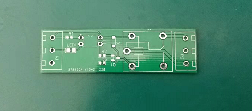
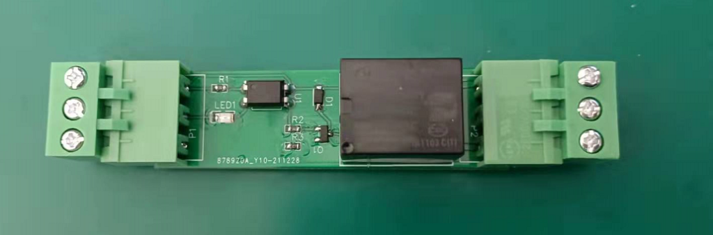
PCB wiring is based on visual wiring, so that it is convenient to view the problem by yourself.
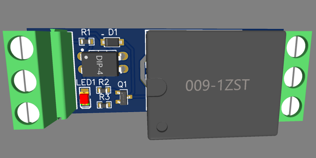
Why should I separate a part at the bottom of the relay?
This is because the place where the coil is generally controlled by the relay is 5V, and the controlled circuit may be 220V. In this case, 220V and 5V are circuit boards, but if the circuit board is hollowed out, the air conductive medium of the air is much smaller than the circuit board.Therefore, it can be avoided. Under the limit, the arc of 220V may affect 5V and transmit it to 5V. In general, in order to reduce the interference of 220V.
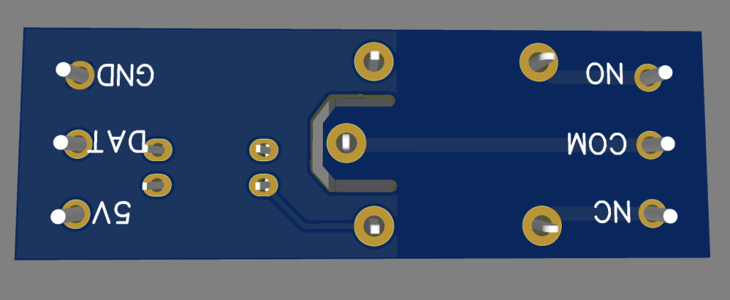
To prevent the dust from absorbing moisture and reduce insulation, in that case, high voltage may affect the weak electric circuit, and this phenomenon can be blocked by slotting.This means "increasing climbing distance".
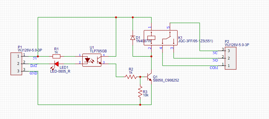
Principles and PCB improvements:
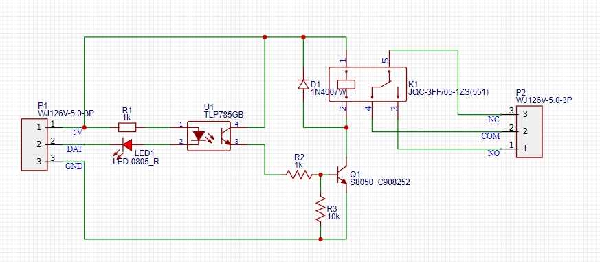
After changing the wiring of the relay, the COM is the public end, the NC is normally closed, and NO is frequent.
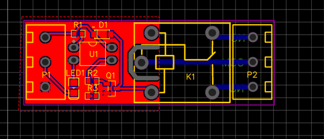
The relay control terminal may be high -voltage, such as 220 volts, which adds slots to isolate, and the width is also added.